
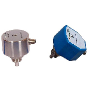
Flow switch
Target flow switch
- Instant response
- Low pressure drop
- Resistance to high pressure
- Repeat the switch more times
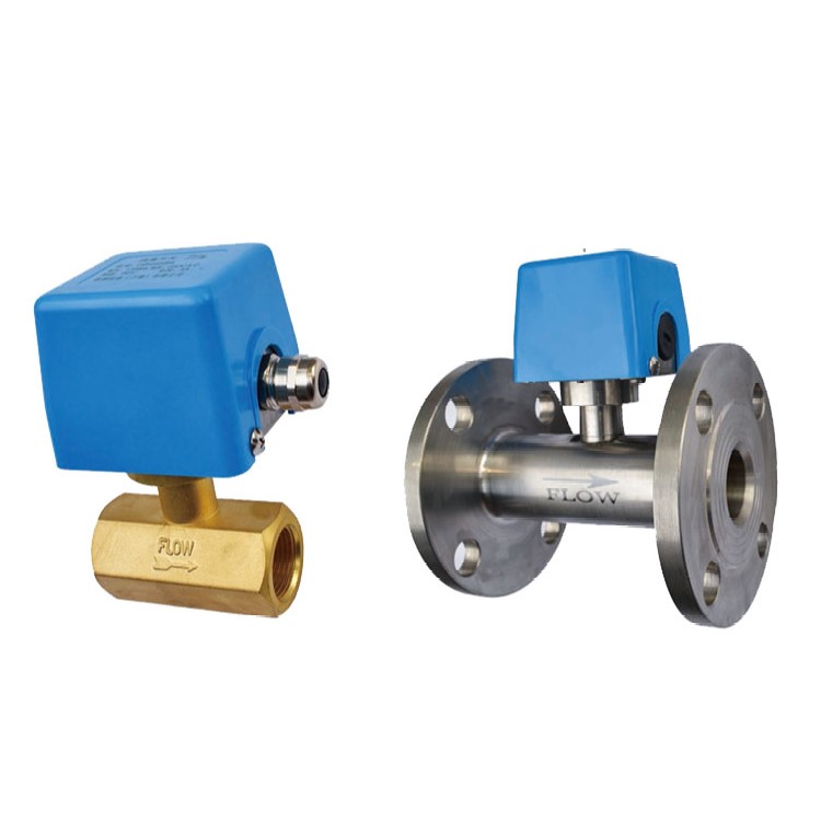
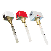
- Product description: RST-01D flow switch adopts target sensor, which can be used in water cooling system or lubrication system as flow control or alarm protection. The setting value of RST-01D flow switch can be adjusted,
I Product introduction
RST-01D flow switch adopts target sensor, which can be used in water cooling system or lubrication system as flow control or alarm protection. The setting value of RST-01D flow switch can be adjusted, and the user can adjust it according to the need.
The moving parts of RST-01D target-type flow switch structure are made of stainless steel to prevent the corrosion of the moving parts and ensure the service life.
II Technical parameters
|
Ambient temperature: |
0℃~60℃ |
|
Medium temperature: |
0℃~120℃ |
|
Pressure: |
1.6MPa |
|
Electric shock capacity: |
A.C.250V10A(resistance) |
|
|
(One set of switching contacts) |
|
Material: |
brass, stainless steel |
|
High temperature and high pressure: |
4.2 MPa |
|
Medium temperature:0℃~320℃ |
|
Size |
Specifications |
Interface thread D |
Flow range |
Switch range |
Repeatability error |
|
|
high |
low |
|
||||
|
15 |
A |
RC1/2" |
3-11 |
2.5 |
1.5 |
2.5% |
|
15 |
B |
RC1/2" |
5-17 |
5.5 |
2.5 |
2.5% |
|
20 |
A |
RC3/4" |
4.2~18 |
3.6 |
2 |
2.5% |
|
20 |
B |
RC3/4" |
8.3~37 |
7.2 |
3 |
2.5% |
|
25 |
A |
RC1" |
5.2~23 |
4.5 |
2 |
2.5% |
|
25 |
B |
RC1" |
10~48 |
9.3 |
4 |
2.5% |
|
32 |
A |
RC1 1/4" |
8.1~39 |
7.5 |
3 |
2.5% |
|
32 |
B |
RC1 1/4" |
19~90 |
11 |
6 |
2.5% |
|
40 |
A |
RC1 1/2" |
15~69 |
12 |
5 |
2.5% |
|
40 |
B |
RC1 1/2" |
25~111 |
16 |
7 |
2.5% |
|
50 |
A |
RC 2" |
35-92 |
14 |
6 |
2.5% |
|
50 |
B |
RC 2" |
46-125 |
18 |
7 |
2.5% |
Note: The flow adjustment refers to the switching adjustment range, that is, the setting value adjustment range caused by switch contact switching when the flow is reduced.
IV Product size

V Installation Instructions
1. Open the flow switch housing;
2. The switch has been set at about the minimum flow value when leaving the factory. Increase the flow setting value and turn the adjusting screw clockwise (1);
3. Press the target to check whether the microswitch can work normally. Too many counterclockwise adjusting screws may cause the failure of the flow switch;
4. After installation, please check the lever by pressing the flow switch several times. Once it is found that there is no "click" sound when the lever returns, turn the adjusting screw clockwise until there is "click" sound when the lever returns;
5. Do not remove the fixing clamp of the adjusting screw, otherwise the flow adjusting screw will fail;
6. Adjustment screw for lacquer seal is only for factory to adjust flow switch state, do not change or adjust;
7. Three working cycles shall be observed to ensure that the switch and the system connected to it operate normally, and the switch housing shall be covered in time.
VI Notes
1. Please carefully check the flow switch before installation. The package should be complete and the appearance should be free from damage and deformation. If you have any questions, please contact the manufacturer.
2. The flow switch can be installed in horizontal pipe or vertical pipe with upward liquid flow direction, but cannot be installed in pipe with downward liquid flow direction. Gravity should be taken into account when installing in a pipe in the flow direction of liquid.
3. The flow switch must be installed on a straight line with a straight stroke of at least 5 times of pipe diameter on both sides. At the same time, it should be noted that the direction of liquid flow in the pipe must be consistent with the arrow direction on the switch housing, and its wiring terminals should be in a position easy to be connected; (figure 1)
4. During installation and wiring, please pay attention to the following matters:
5. Absolutely forbid the wrench to touch the switch floor, resulting in the deformation and failure of the flow switch;
6. In order to avoid electric shock and damage to the equipment, the power should be cut off during wiring or debugging;
7. When wiring, it is absolutely forbidden to adjust other screws except microswitch wiring terminals and ground screws. It should also be noted that the microswitch should not exert too much force when wiring, otherwise it is easy to displace the position of the microswitch itself, resulting in the failure of the flow switch;
8. Special grounding screws must be used for wiring, and installation screws cannot be removed at will, otherwise the controller will be deformed and fail;
9. The target of the flow switch should not be in contact with the inner wall of the pipe and other restrictors in the pipe, otherwise the switch could not be reset normally.
RELATED PRODUCTS
CATEGORIES
LATEST NEWS
CONTACT US
Contact: Andy.Zhang
Phone: 86+18816633390
Tel: 86+0532-86888236
Email: qdrstsuto@qdrstauto.com
Add: No.7, Siliu Middle Road , Licang District, Qingdao City, Shandong Province, China